Adapting integrated laptop cameras to USB
Did you know that most laptop's integrated cameras are actually USB cameras and can be easily converted to stand-alone units? Although most of them, especially the ones found in lower-end laptops are relatively cheap modules with a low resolution and poor framerate, their slim shape and compact form still makes them the ideal choice for countless applications.
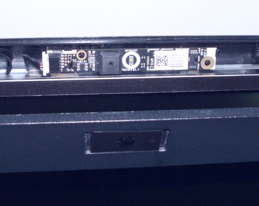
For example, I recently got an older broken Compaq laptop. Looking at the integrated camera's specs was obvious that it's a low-end module, but for my intended use it was the perfect gadget.
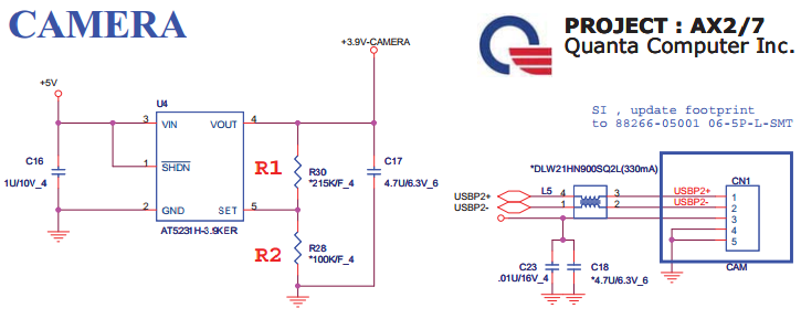
There was 3.9V printed on the PCB, so it was obvious I needed to build a simple voltage regulator. I found the laptop's service manual and sure, it uses an AT5231H-3.9KER IC to drop the voltage. Unsoldering this IC from the motherboard and reusing it, together with the small components around it would have been the easiest option, but I decided to use a standard LD1117 (SMD) adjustable version regulator instead that I had laying around.
The LD1117 has a typical dropout voltage of 1V (and a maximum of 1.1V) at 100mA, so producing a stable 3.9V from 5V is quite at the edge of its capabilities. In my case, the camera was to be plugged in into a self-made externally powered USB adapter that has a 5.2V supply line, so I was sure it will regulate properly. Update: after extensive tests I can confirm that it works perfectly even when plugged into a standard USB port.
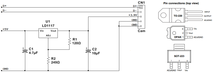
Only SMD components were used. To maintain the compact form, the circuit was built directly on the camera's PCB, using my "freestyle" method. I used the small ground areas between the module's connector and CCD to fix the regulator IC to the PCB. Because the IC has no direct connection to the ground, I soldered small 100nF SMD capacitors upright, with one pin to the ground and the other to the legs of the IC, providing a pretty solid support. R2 and the two tantalum capacitors strengthened the circuit further. R1 was soldered directly on the IC's legs. This type of construction does not look good, it's not that robust, but it does its job, and for non-critical applications like this one is perfectly fine.
So the moment of truth: plugging in. No worries, W10 instantly recognized it as a “HP Webcam-101”. Let's start VLC! After selecting the camera, I've got a superb picture. Easy?
Adapting other integrated cameras
Although this camera required 3.9V, you'll find that other models will need voltages ranging from 2.7V to 5V, so each model demands its own solution. Obviously, 5V units are the easiest to adapt, you just need to locate the V+, data and ground pins and solder on the USB cable.
Almost every lower-voltage module will run perfectly on 5V, but most probably will severely overheat and eventually fail. If you don't have the patience to build a standard voltage regulator, at least insert one or two rectifier diodes in series with the 5V line. Standard Si diodes like the 1N4001 have a voltage drop of around 0.6V and Schottky diodes have a voltage drop of 0.15V-0.45V. You can experiment and mix them to achieve the desired voltage. This solution is not perfect, but way better then running the module on a greater voltage.
Identifying the pins
Consulting the laptop's service manual is the easiest, but if you don't have it at hand, identifying the pins is not that hard. Some modules have most pin's names printed near the connector. If not, you must do some basic reverse engineering.
First, you'll localize the ground pin(s). Find the module's ground: usually this is connected to a large copper area, for example, around the mounting holes. Test each pin with a multimeter. Every pin that shows 0 ohms against the GND is a ground pin.
Next, locate the data pins. These are easy to identify too, as they usually have thin traces, run in parallel, and have symmetrical circuits. If you have the module's cable, these are usually twisted together. The tricky part is identifying the polarity. Data cables have usually respect the standard color coding and use green for D+ and white for D-, If not, that could be easily solved in the final stages of the construction: if after plugging in, windows complains that the device is not functioning properly, just exchange D+ and D-, and you're done.
After that, only 1-2 pins will be left unidentified. If it's only one left, that's definitely the V+. If not, you probably have a module that needs “enable/disable” signals you'll need to connect either to V+ or GND through a small resistance. Still, you could identify V+, as it usually have a wider trace, probably has a smoothing capacitor connected to it with the other side going to the ground, etc. Enable/disable pins probably have a thinner trace and usually have small resistances in series/connected to V+ or GND.
Construction
I usually mount all the required components on the module's PCB, remove the connector, and solder the USB cable in directly. This yields an extremely compact unit, but is quite difficult to build. The easiest way is to keep the connector and a few inches from the module's original cable and etch a small PCB for the regulator with contacts on one side for the camera's original cable, and on the other side for the standard USB cable. For 5V modules will not even need soldering, just twist the wires together and carefully isolate each contact.
A small metal/plastic box is not necessary, but recommended. I usually fold at least a basic plastic box around the module to protect the improvised adaptor circuit.