Bluetooth Mini-PCIe module to USB adapter
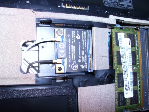
After receiving an old broken Compaq CQ56 laptop that was not worth the cost of repair I started to look what could I salvage from it before scraping. I usually keep the hard disk, the camera module, microphone, WIFI cables/antennas and a few discrete components from the motherboard / the motherboard itself.
This laptop also had a nice looking WIFI/Bluetooth module. After a close look at its pins, I observed that it has its USB data pins (36 and 38) connected internally, so there is a good chance that it could be adapted to a stand-alone USB dongle. After doing a little research, it seems that only the Bluetooth part can be controlled from USB, the WIFI part still needs the full PCIe interface. The project still worth doing, as the it only takes a few hours of work, and after that I will own a nice, sensible and powerful Bluetooth dongle, and most importantly, one with a replaceable external antenna, which is not easy to find this days.
So what we'll need for this project? A short USB cable, a 3.3V voltage regulator, two small smoothing capacitors, a soldering iron/solder and a little effort.
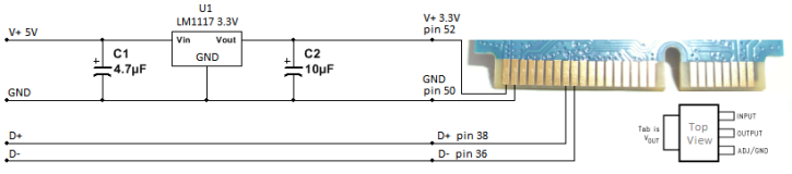
I decided to solder the parts directly to the module, instead of etching a PCB for a mini-PCIE connector. I used a small ground pad near the module's V+ pin to solder the regulator's ground lead to. That, together with the middle pin connected to the V+ (pin 52) and the smoothing capacitors connected to the input/output pins yielded a pretty solid construction.
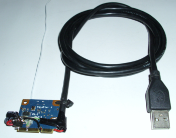
After aligning the data lines with the corresponding pins, a small drop of superglue was used to fix them to the PCB, as this made it easier to solder them to the tiny pins later on.
The USB cable's shield was soldered to a small ground area on the other side of the module and also fixed in place with a small wire further up.
After plugging in, the Bluetooth adapter was instantly recognized by Windows, and it seems to work perfectly. The power regulator was a bit warm after a few minutes of use, but not too hot to the touch. I will leave it on longer and if it gets too hot, I will solder a small copper heatsink to the middle pin connected to the module's V+.
Another thing that could improve the dongle would be a small blue LED indicator connected to pin 46.
The whole module will be placed in a small metal box with a tiny whole for the LED and will be equipped with a standard WIFI antenna connector.
As you can see, the adapter is quite easy to build. I've seen a few projects done by brave DIYers on the net, successfully adapting Bluetooth, 3G/4G and other modules. There are also cheap commercial adapters on sale online, so if you're not into electronics, maybe ordering one is a better option.
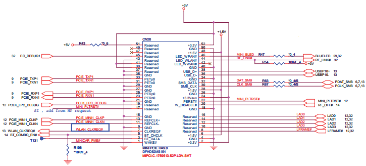
| Table 1: WIFI/Bluetooth module (RT3090BC4) connector pin-out | |||
|---|---|---|---|
| Pin | Definition | Basic Description | Type |
| 1 | NC | No connect. Should be left open. | |
| 2 | 3.3V | 3.3V power supply | VCC |
| 3 | NC | No connect. Should be left open. | |
| 4 | GND | Ground | GND |
| 5 | Radio DISABLE_L | BT disable control (Module default pull high, Module Internal 10K Resister Pull-High) | Input |
| 6 | 1.5V | The pin is defined according to PCI-E standard. Note: this module does not use power source 1.5V. | VCC |
| 7 | CLKREQ_L | Reference clock request. | Output |
| 8 | NC | No connect. Should be left open. | |
| 9 | GND | Ground | GND |
| 10 | BT_APM | CSR APM (Advanced Power Management) | Output |
| 11 | REFCLK- | Differential reference clock | Input |
| 12 | NC | No connect. Should be left open. | |
| 13 | REFCLK+ | Differential reference clock | Input |
| 14 | NC | No connect. Should be left open. | |
| 15 | GND | Ground | GND |
| 16 | NC | No connect. Should be left open. | |
| 17 | NC | No connect. Should be left open. | |
| 18 | GND | Ground | GND |
| 19 | NC | No connect. Should be left open. | |
| 20 | Radio DISABLE_L | WLAN disable control. (Module default pull high, Module Internal 10K Resister Pull-High) | Input |
| 21 | GND | Ground | GND |
| 22 | PERST_L | PCI express fundamental reset | Input |
| 23 | PERn0 | Differential transmit | Output |
| 24 | 3.3VAUX | The pin is defined according to PCI-E standard. Note: this module does not use power source 3.3VAUX | VCC |
| 25 | PERp0 | Differential transmit | Output |
| 26 | GND | Ground | GND |
| 27 | GND | Ground | GND |
| 28 | 1.5V | The pin is defined according to PCI-E standard. Note: this module does not use power source 1.5V. | VCC |
| 29 | GND | Ground | GND |
| 30 | NC | No connect. Should be left open. | |
| 31 | PETn0 | Differential receive | Input |
| 32 | NC | No connect. Should be left open. | |
| 33 | PETp0 | Differential receive | Input |
| 34 | GND | Ground | GND |
| 35 | GND | Ground | GND |
| 36 | USB_D- | USB Differential signal | Output/Input |
| 37 | GND | Ground | GND |
| 38 | USB_D+ | USB Differential signal | Output/Input |
| 39 | 3.3VAUX | The pin is defined according to PCI-E standard. Note: this module does not use power source 3.3VAUX | VCC |
| 40 | GND | Ground | GND |
| 41 | NC | No connect. Should be left open. | |
| 42 | NC | No connect. Should be left open. | |
| 43 | GND | Ground | GND |
| 44 | LED_WLAN_L | Active low signal. The signal is used to provide status indicators via LED. | Output |
| 45 | NC | No connect. Should be left open. | |
| 46 | LED_BT_L | Active low signal. The signal is used to provide status indicators via LED. Status indicators via LED. | Output |
| 47 | NC | No connect. Should be left open. | |
| 48 | 1.5V | The pin is defined according to PCI-E standard. Note: this module does not use power source 1.5V. | VCC |
| 49 | NC | No connect. Should be left open. | |
| 50 | GND | Ground | GND |
| 51 | NC | No connect. Should be left open. | |
| 52 | 3.3V | 3.3V power supply | VCC |